When you click on links to various merchants on this site and make a purchase, this can result in this site earning a commission. Affiliate programs and affiliations include, but are not limited to, the eBay Partner Network.
H2 Driver seat not working - Burnt connector - need wiring help
Hummer H2For those who like a little more gleam to their Hummer, the H2 offers a similar rugged look as the H1, but as a lower cost, and with more added features, making it almost a massive luxury SUV.
Pulled up an '07 connector End View and go this:-
Is this drawing the same as yours?
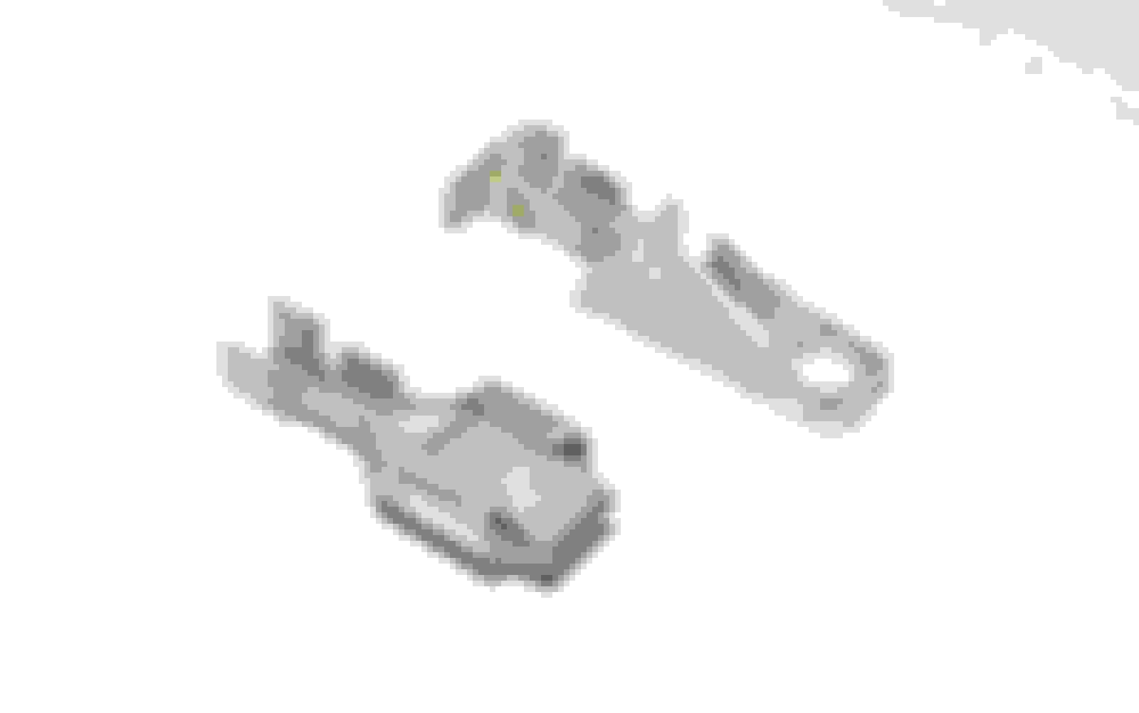
If so, the left female connector 15336219 (Shell) and is available here and the right here both are in stock, Mouser also have pins for both sides here but I'm not sure of the exact ones (yet)
Anything I can do to help, I have an account with mouser, but I think to can order direct using your card.
If you don't have one, you might need a crimping tool if you go this route, the manufacturer ones are expensive but this one would probably do and it will work form most types of crimps
👍
With your help, I located the Delphi/Aptiv connectors, and the list of the 150 (small) and 280 (large) series pins that fit into these. However, I have no idea about how to interpret the "cable range" that these pins are sized in. Does "cable range" refer to the wire itself, or the wire+jacket? I believe it is the wire only, and they use mm2 instead of AWG.
So all I need to figure out is what is the gauge of each wire in that connector.
Would you have a wiring diagram handy that would show the wire thickness of all the wires going thru that connector?
It should be in the shop manual, but I can't locate it. Most wiring diagrams show the gauge + color. I did manage to stumble upon pin B pink wire size at 0.8 mm2 (about 18 ga) on one of the schematics in the shop manual. Not sure how to locate the "Circuit numbers" on the list you provided. If you can tell me that, then I should be able to figure out the correct pins required.
Also update: once I looked at the connectors again a few times, I realized that the color of the wires are in the CORRECT location on the connector. As per your diagram above.
I have to figure out the pin part numbers and wire sizing, before I can try to order from Mouser.
The crimping tool you pointed me to, will work well. I only have a basic one which does not do open barrel terminals.
From Japan to here in Canada, about $100 Canadian. Bit steep, but I will swallow the cost. Thanks for the lead.
I also located an interesting tidbit from Delphi, regarding temperature curves.
Seems to me that these are the WRONG connectors for this high AMP seat heater application.
No wonder they are melting! They are not rated for these loads. No margin of safety.
If so obvious to me, why not so obvious to GM wiring harness designers?
American Wire Gauge (AWG) relates to the diameter of the wire or wire bundle (excluding insulation). As insulation thickness (jacket) depends on the application e.g. high voltage with thicker insulation, it's difficult determine the AWG by measuring the sheath alone, unless there's a sample to work from.
I trawled through all my diagrams, but could nothing relating to specific colours or circuit numbers, has to be somewhere.
Glad the colours matched-up, that's one less thing to worry about 👍
This chart provides some key data e.g. AWG, diameter and current capacity, there's also a visual chart (note AWG is the inverse of size)
I did find this chart in the '04 wiring diagram, suggesting these are the sizes GM uses:-
So for the following Mouser Pin sizes (ranges):- AWG Min | AWG Max | Dia Min | Dia Max | Current Max GM AWG
12 10 0.0808" 0.1019" 15A 10
15 12 0.0571" 0.0808" 9.3A (10A) 12
16 13 0.0508" 0.0720" 7.4A (8A)
17 14 0.0453" 0.0641" 5.9A (6A) 14
18 15 0.0403" 0.0571" 4.7A (5A)
I'm guesstimating 14AWG - 6A, 12AWG -10A, and 10AWG - 15A will be the matching GM sizes (but I have no proof)
The thickest wires in connector (such as Orange & Black) are most likely 15A 10AWG i.e. the largest available pin size (it looks maxed out in your pictures)
The Pink. Blue and Light Blue wires could be the next size down e.g. 10A 12AWG and the others possibly 14AWG
If the seat isn't working you could always snip one off and measure with calipers.
If you google "hozan p-706" you might find a cheaper source for the crimp tool, it's worth a look.
The crimp-pins look almost flush with the connector body, so if there's enough spare length you could snip-off each wire, one at a time, crimp and fit in the shell.
Note once in the shell they are difficult to remove, I speak from experience (then you'll need your tool)
Forgive me if you already know this, but there's an "art" to crimping wires and getting the flanges to "curl in" and grip the wire and insulation.
The crimps usually have two sets of flanges, the smaller inner flanges grip only the bare wire. When formed they should "curl-in" and fully envelop the wire, which shouldn't pull out.
The outer larger flanges tend to "bite" into the insulation to secure the wire further.
There should be no free strands and it should look neat and firm.
Start with a slightly larger crimp size first to get the curl started, then finish-off with the best matching smaller size. If you go too small you'll find the tool will cut-off the flanges, so avoid overdoing it.
The same technique works for the insulation, you'll see from the existing old pins what the end result should look like.
Best to practice using some spare wire and crimps to get the "feel"
Your observations on temperatures are indeed born out by reality, there is obviously a miscalculation there.
An small increase in contact resistance can cause disastrous problems as heat is generated according to a square law (I�R)
Even greasy fingers can corrode contacts which increases resistance with time and heat. The more corrosion, the more heat and so on - catch 22.
Bad joints (the electrical ones) can have the same effect, it's how fires often start.
BTW my truck is an '05 Canadian import, 1st registered June 2006.
Out of interest, have you been following the convoy?
Seems an amazing what's going on in Ottawa.
P260 of the '04 manual Fig 42 STUD 1, STUD 2, VSES/ECAS, BLOWER, ABS, and MBEC 1 Fuses, RT DOORS and SEATS Circuit Breakers Schematic
shows circuit 1440 (30A Circuit Breaker Power 12V) as Orange "3" which I believe is 3mm� 12 AWG and specificallyC325
P280 Fig 62 G302, G304, and G306 Schematic
shows circuit 1150 G302 (GND) as Black "3" again which I believe is 3mm� 12 AWG and specificallyC325
On that same ground G302 it also shows 1150 wiring with 0.35mm� 22AWG, 0.5mm� 20 AWG, 0.8mm�, 18AWG and 2mm� 14AWG but none go to C325
See attached PDF
Most of my wiring pdf is not "searchable" I'm gradually overwriting as I work on it, but is a real pain I have to say.
So It looks like the power wires are 12AWG which is a start
The large terminals are gm56 series. Go to your local auto parts store and get 14-16ga Or 12ga(take an old terminal to match) m/f terminals. Replace the damaged terminals, crimp and insert into current connectors.
((((((((Make sure to clean the remaining terminals too)))))))
Thanks for your help @oceanbrave I owe you a pint, and we had planned to visit the UK, but now that has to wait sometime after Covid is done with.
You are correct, I will pull out any pins I can, and likely just replace the burnt ones. I will still get that tool, for future use. And extra pins just in case some break on extraction.
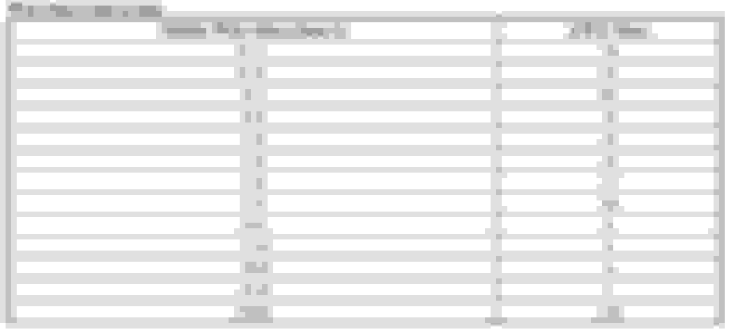
I have done a ton of research this morning. Finally found some relevant wiring diagrams in the 2007 shop manual on page 14-91
Here are the wire sizes:
Circuit.............size mm2
1440 3.0
2480 0.8
1048 maybe 0.35, but not specific for that connector, only for driver side memory seat module
238 ???? HELP
2433 0.8
2479 1.0
1363 ???? HELP
2434 0.35
2435 0.35
1150 maybe 3.0, but not specific to that connector, only for driver side memory seat module
So I really need help identifying circuit 238 (left seat belt switch) and 1363 (low reference ??). The rest should be OK.
The 1150 circuit you found on your Fig. 62 does show the 1150 wire to be 3.0 mm2 in the C325 connector, so that confirms that one.
My 2007 schematics are really, really poor, with lots of labeling missing. It only shows it going to the module, but not thru the C325. So glad you found this on yours.
Looks like the 30A feed thru the 1440 circuit orange wire, and the 1150 black ground wire are the ones that are heating up and melting the connector.
Also while googling, I noticed the same problem in Escalade and other GM vehicles. Same crappy connector.
Go to your local auto parts store and get 14-16ga Or 12ga(take an old terminal to match) m/f terminals. Replace the damaged terminals, crimp and insert into current connectors.
These are very specialized tiny connectors, in very special wire gauge sizes, and critical overall size to slip into the exact connector they were designed for. The C325. And require a special open barrel crimping tool. And not available in auto parts stores. Only online via Delphi/Aptiv manufacturer.
Once I identify the proper ones, I will post all the part numbers for the pins and connectors here for the next person who will have to do this to their H2 sooner or later if they use seat heaters regularly.
@finall ... actually I think you are there so to speak.
Good chance Pin-A 1440 and Pin-S 1150 are the same AWG, they are on my diagram and besides if the Black wire is 10 AWG it will be the same crimp anyway (i.e. max)
Now you've identified most the other wires and their gauges i.e. 0.35, 0.8 and 1, you can use a vernier to match the rest as they are likely to be a member of that same set.
Pin-D 1048 (Brown+White) is Class 2 Serial, so low current and very likely 0.33 / 22 AWG as you quote.
Pin-J 1363 (Dark Blue) Low Reference may well be 0.8 (looks like it from your pics) It's the ground ref for the two temperature sensors, makes sense they would make it thicker.
Pin-E 238 (Black+White) Seat Belt Switch looks to be the same size as 1363
My pdf's are poor too, but I think you've cracked it...
 01-31-2022, 10:25 AM