When you click on links to various merchants on this site and make a purchase, this can result in this site earning a commission. Affiliate programs and affiliations include, but are not limited to, the eBay Partner Network.
H2 Driver seat not working - Burnt connector - need wiring help
Hummer H2For those who like a little more gleam to their Hummer, the H2 offers a similar rugged look as the H1, but as a lower cost, and with more added features, making it almost a massive luxury SUV.
H2 Driver seat not working - Burnt connector - need wiring help
Well, I have now experienced what many of you have. An inoperative driver seat with these conditions:
1. No power functions on driver's seat.
2. No seat heater driver side
3. No seat heater passenger side.
Happened during an unusually cold weather. ie. was using both front seat heaters a lot at the time.
I immediately thought it may be the large power connector, which is anchored to the floor by a metal bracket. It is covered by a plastic snap-on cover, with tangs on each end.
Because I experienced this with our previous 06 H2 on which it happened quickly, and which the dealer repaired 14 years ago. Not sure how they fixed that one, but I think they mentioned that they jumped some wire.
With that knowledge, I wiggled the wires on the intact connector, and power to everything came back on.
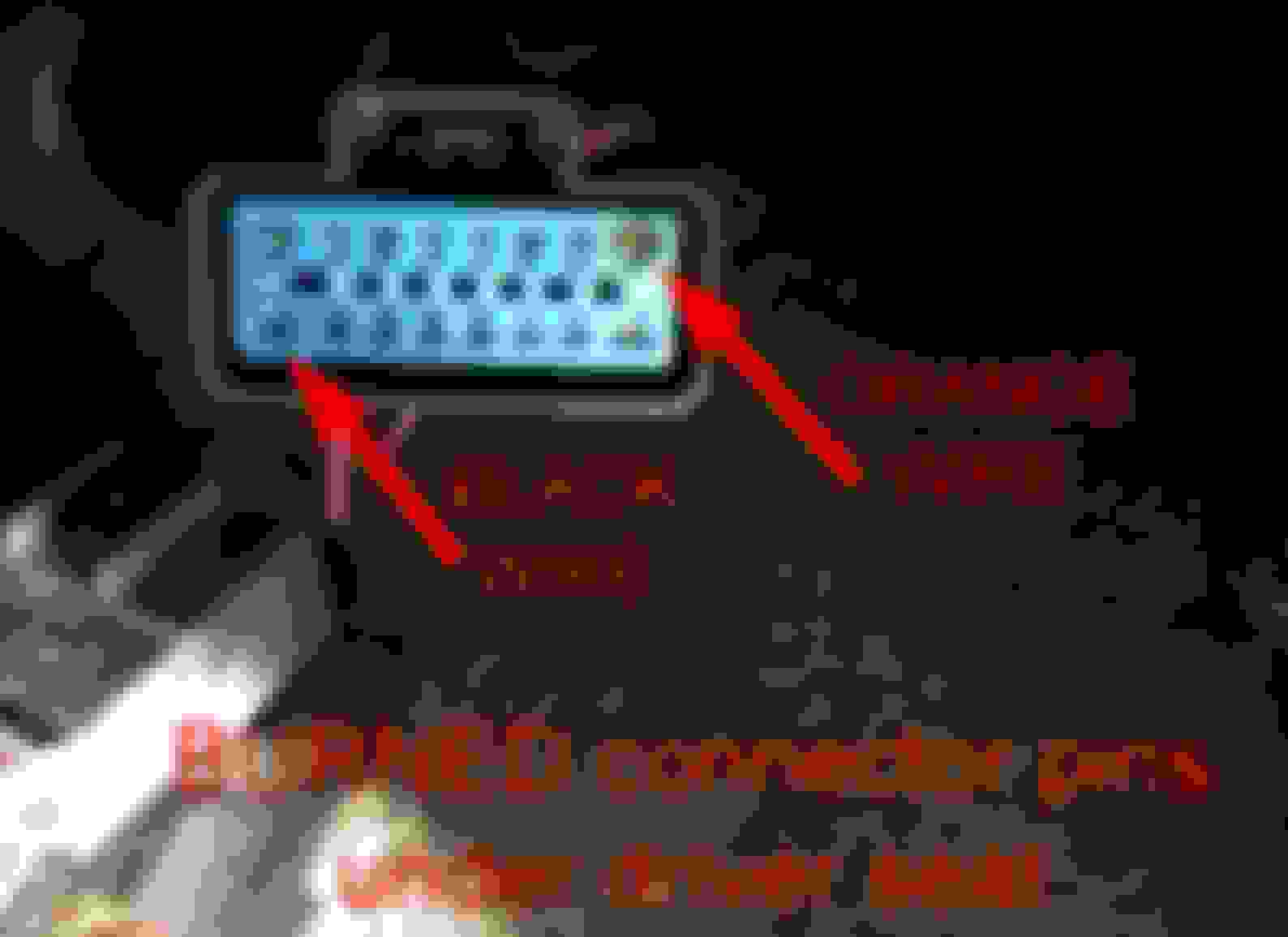
Later, I took the connector apart. Attached photos show what the problem is.
The large orange and black wires going into the connector have burned connector pins.
Q. What does the fat orange wire power?
Q. What does the fat black wire power?
Q. Anyone know the gauge of these 2 wires? (info I will need if I splicing in new wire)
Q. And what the heck is drawing so much juice, to melt these connectors? Granted, the connectors are really skinny, but the only thing there are the 2 seat heaters.
Another question: I could not find a fuse for the FRONT seat heater circuit. I think there must be a relay or fuse somewhere, but I can not see one for just that particular circuit.
I see on for the REAR seat heaters, but not for the FRONT seat heaters.
Repair options:
1. The easy fix is to jump the wires across this connector, by splicing in a longer wires and bypassing the connector.
That also necessitates each wire having its own connector, so that the seat can be removed when required.
And that can just repeat the problem on each wire and its own connector. Unless larger spade connectors will generate less heat.
2. But is there a more elegant fix? Something better, nicer, more OEM looking, etc.
I have some thoughts, but want to hear your opinion please.
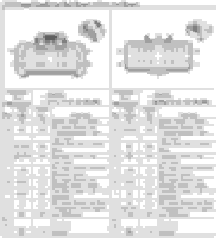
The diagrams are hard to follow and I had a hard time matching the 16-Way connector to any wiring diagram pin-out, however I did find something similar, the colors seem to match but with the bottom row reversed.
Notice
Pin-A = Orange
Pin-B = Pink
Pin-C = NU
Pin-D = Brown+White (yours looks Gray+White but could be lighting)
Pin-E = Black+White
Pin-F = NU
Pin-G = LightBlue
Pin-H = DarkBlue
Reversing J-S (bottom row)
Pin-J = DarkBlue
Pin-K = Gray (Looks white in jpg)
Pin-L = Can't see but could be Pink
Pin-M to R = Can't see
Pin-S = Black (Ground)
This of course may just be coincidental but it's odd the colors seem to match.
This is the diagram I found:-
For your 1st + 2nd questions, It looks like the Orange wire is circuit 1440 and connects to the 30A Seats Circuit Breaker and the Black wire probably goes to ground
3rd, The AWG (American Wire Gauge) can be calculated (see this link) if I had to guess I'd say 12 AWG
4th You are correct, primarily it will be the seat heaters plus any active motor currents.
It's a strange phenomenon with connectors and contacts, basically heat is generated by contact resistance caused by a poor wire crimp, ageing, surface corrosion or contamination from fingers or oils. But here's the problem, as contact resistance increases, more heat is generated accelerating the surface corrosion, thus causing more resistance and more heat etc. It's a catch22 scenario.
Consider this, heat generated W = I�R where I=Amps, R= Ohms, W=Watts, when R=0 i.e. a perfect contact, Watts=0. Suppose the Driver's seat peaks a 10A and R = 0.01 Ohms, then heat generated is 10*10*0.01 = 1 Watt, if R increases to 0.1 then it's 10Watts enough to solder with!
Re Repair Options
My initial reaction is not to "bodge" the repair and replace/repair the connector if possible.
Looking at your images, the female connector looks bad, but the male shows only mild scorching, you could probably clean-up it's pins with a fibreglass pencil of small ink-eraser and then degrease with IPA (most important I�R)
Not sure I have the correct connector, but it could be the the 16-Way F GT 150 280 shown above (see eBay connector) but I'm not convinced, the connector looks more "rounded" and sealed and yours looks square and not sealed (didn't need to be)
So it would be a matter of tracking down the right connector, it's surely and Aptiv (formerly Delphi) connector, but there are many types. I've just looked on Mouser and spotted this one which the unsealed variant of the above, it looks more similar, unfortunately can't find them on eBay. This would be a 16-Way F GT 150 280 Unsealed, Mouser has the Data sheet so you could check its dimensions, you'll also need pins.
Another possibility is that the pins between sealed/unsealed connectors are the same (don't know for sure) that being the case it may be possible to extract the burnt pins and replace just the bad ones.
Take a closer look at the connectors and see if you can find the P/No's again I'm not sure about the ones I've suggested, the Mouser one has a gap/segment in the middle.
Without more data they may be hard to find, you may have more joy tracking down the pins than the shells. It looks like 150 280 means there are mixed pin sizes, as opposed to all 150 or all 280. Of course the connectors may well be obsolete.
I'd be tempted to use an extraction tool (small pin) to remove a crimp-pin, check the size and then buy a pack of female crimps (again possibly these)
Try removing a good crimp-pin first to develop the technique (
1 no stock anywhere on earth!
2 Is available
3 is available.
The online information is confusing, there seems to be only 1 type of male connector for the sealed and unsealed series, but two females versions in each. It looks like the females come either even as yours (15339999) or offset (15336224) it's possible the male might mate with either (no idea why?)
Condition
Some customers may comment that the seat heater and/or memory seat functions are inoperative.
Cause
A logic lockup of the memory seat control module may cause this condition.
Correction
Important
This repair is not to be performed on vehicles without memory/heated seats. If the vehicle does not have memory/heated seats but has an inoperative power seat, use published Service Information to diagnose the concern.
If the seat is currently inoperable, perform the following diagnostic steps to determine if replacement of the memory seat control module is the correct repair:
Connect a Tech 2� to the vehicle and monitor the parameters in the sensor data list for the driver seat module as you try to move the seat. Are the displayed data parameters changing, or does the Tech 2� display no communication as the seat switch is moved to various positions? If the data parameters do not change, the memory seat control module may be inoperative due to a logic lockup.
Remove the SEAT circuit breaker in the instrument panel relay block located under the left side of the instrument panel next to the parking brake. This circuit breaker also supplies power to the passenger seat.
Verify that the circuit breaker is not open. If it is not open, wait 30 seconds and then reinstall the circuit breaker.
Try to move the seat again.
If the seat moves or the data parameters displayed on the Tech 2� change when the seat switch is activated, replace the memory seat control module. Use the Memory Seat Control Module Replacement procedure in SI.
If the memory seat is still inoperative, use normal Service Manual diagnostics to determine the cause of this condition.
Parts Information
Part Number
Description
Qty
15196666
Module, Memory Seat
(HUMMER H2, Cloth Seat, RPO 50D)
1
15196667
Module, Memory Seat
(HUMMER H2, Leather Seat, RPO 502)
1
15196668
Module, Memory Seat
(Full Size Pickups, with AN3, w/o JF4)
1
15196669
Module, Memory Seat
(Full Size Utilities, with AN3 and JF4)
1
Parts are currently available from GMSPO.
Warranty Information
For vehicles repaired under warranty, use:
Labor Operation
Description
Labor Time
N5510
Module, Memory Seat System Components-Replace
0.4 hr
Add
Diagnosis Time
0.0-0.3 hr
N5510
Module, Memory Seat System Components-Replace (HUMMER H2 Only)
ST
Well, I found the correct pinout diagram for the C325 underseat connector for an 2007 H2.
It was in the 2007 shop manual, and I would never have found it there without your initial help with the connector #.
Same as the diagram you posted.
EDIT: My wiring is the same as the connector schematic you show.
Also, this connector is still available from GM, but only with wires on one side (not the other), and cost is over $120 USD for the side with the wires attached. I guess designed to be spliced.
Ouch. And it still means lot of work pulling the pins out if you do not want to splice.
The other side is about $5, without wires. Which is incongruent to the way they supply the other side.
This is as far as I have had time to deal with it. Still waiting for my pin removal key set from China....